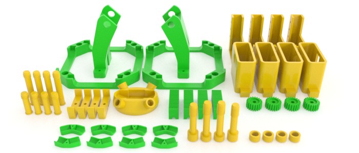
Total Print Time: 3,560 min. (59 hours 20 min.) at 4,800 mm/min.
Total Filament Required: 867 gr.
NOTE:
- To use the servo motor TowerPro MG996R instead of Hitec HS-311 (see hardware list below), print rcr_pinion2.stl instead of rcr_pinion.stl.
- If your 3D printer has a large enough print platform, print 2 of rcr_4corners.stl instead of 8 of rcr_corner.stl.
Hitec HS-311 Servo Motor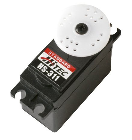
OR
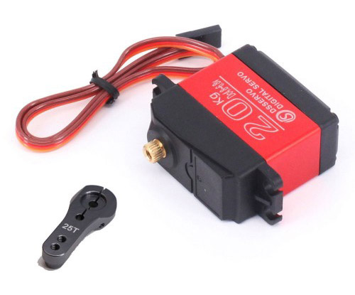
TowerPro MG996R Servo Motor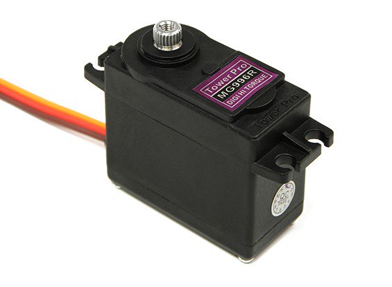
USB HD 12 Megapixel Webcam with a Clip
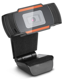
Search on eBay, Amazon, etc. for Webcam and look for this distinctive shape.
Wall-plugged 6V, 3A (3000 mA) charger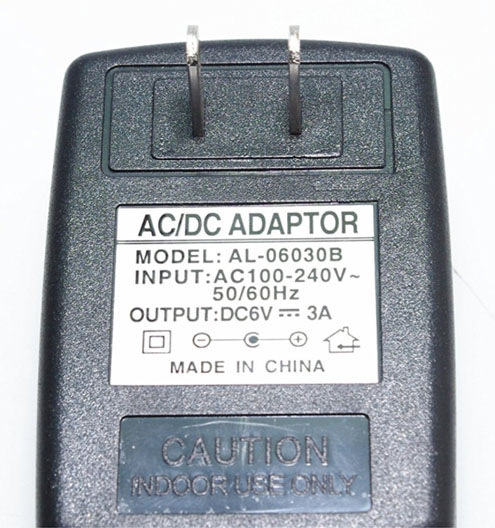
Our robot uses the SMAKN power supply adapter (shown here) together with a DC female adapter (see next item) and two male/female jumper cables to be plugged into the Pololu servo controller.
DC 5.5x2.5mm Female "Balun" Adapter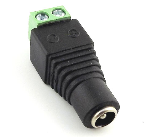
This very inexpensive little adapter will help you power your robot without soldering! Plug the wall charger into it, insert two jumper cables in the other end and tighten the screws. See Section 7 - Connecting Electronics for more info.
Standard-Size Rubik's Cube
Without this item, the robot is completely useless. We recommend the stickerless, smooth-operation variety. Our color recognition code was only tested with the standard (original) colors shown here. Please do NOT use a speed cube!
Small 2mm Wood screws or Metric M2x8 Bolts
These are to attach the HS-311 horns to the servos, and two more to attach the Pololu servo controller to the back side of the camera holder.
Hair rubber bands (optional)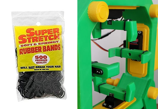
Putting two tiny and extremely cheap rubber bands over each gripper greatly increases friction between the holding grippers and cube, and dramatically reduces the chance of the cube being accidentally dragged sideways by a retracting gripper.
Total Cost of Hardware (approx.): $150.00 - $200.00.
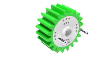
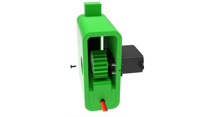
Attach the round horn that comes with the HS-311 servo to pinion with two small 2mm wood screws or two metric M2x8 bolts. If you are using the TowerPro MG996R servos, use rcr_pinion2.stl instead of rcr_pinion.stl as the black round servo horn that comes with the MG996R is smaller and has the mounting holes closer to the center.
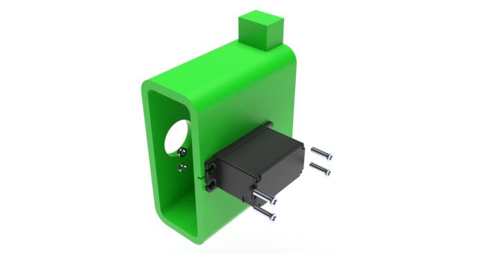
Insert the single-armed horn that comes with the DS3218 servo into gripper. Secure with two metric bolts. Screw in the bolt closer to the center first.
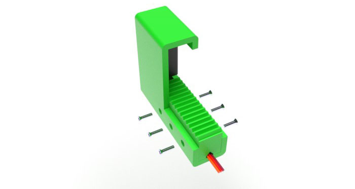
Insert the DS3218 servo into slider. Secure with 4 metric bolts and nuts.
Insert rack into slider, have the servo cable run in the triangular recess in the bottom of the rack. Align holes. Secure with 6 metric bolts.
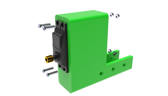
Insert the HS-311 servo into arm. The servo's shaft must be aligned with the round hole on the other side of the arm. Secure with 4 metric bolts and nuts.
To secure the slider in place, install the pinion onto the HS-311 servo's shaft and secure it with an axis bolt that came with the servo. Note that during the calibration phase the pinion may need to be removed, slider adjusted, and pinion replaced.
Repeat Steps 1 to 6 to assembly three other arms.
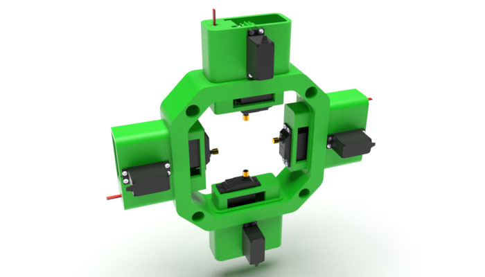
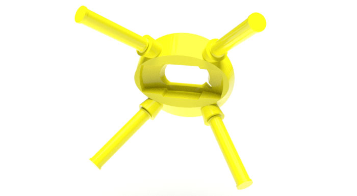
Step 7:Using the 8 corners (rcr_corner.stl) or two 4-corner frames (rcr_4corners.stl), assemble the 4 arms into a single unit.
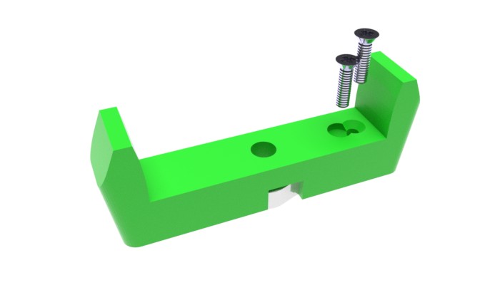
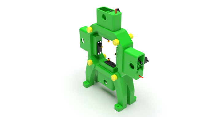
Set the assembly obtained in Step 7 onto the two legs, align holes. Insert the pair of long_bolts in the bottom holes, and short_bolts into the top holes. Secure all 4 bolts with nuts. The heads of the bolts must be on the same side as the HS-311 servos (far side on the picture below), while the nuts on the opposite side (near side on the picture below.)
Screw four short rods (rcr_rod_short.stl) into the heads of the long and short bolts tightly.
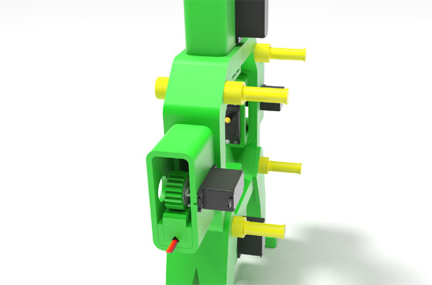
Screw four long rods (rcr_rod.stl) into the slots of the camera holder tightly.
Position the camera holder in such a way that the ends of the rods attached to it are in close proximity to the ends of the rods attached to the main unit. The slit in the camera holder must point downwards. Using the clamp_halves, connect the 4 pairs of rod ends. Secure the clamp halves with the metric bolts and nuts.
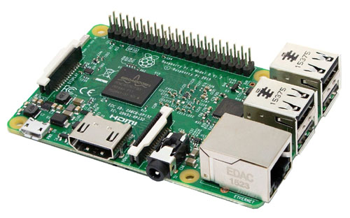
Detach the camera body from the clip: remove two small round stickers covering a pivot bolt connecting the camera to the clip, and then unscrew the bolt with a screwdriver. Plug the camera into Raspberry PI's or PC's USB port. Install the grippers onto the DS3218 servos, secure with axis bolts that came with the servos. Do not tighten the servo horn clamps just yet as the positions of the grippers may need to be adjusted during the calibration phase.
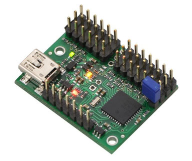
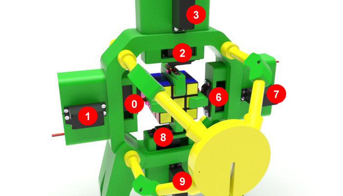
The servos can be connected to any of the 12 channels of the Mini Maestro arbitrarily. The image below shows the channel assignment used by our robot. A white number in a red circle next to a servo denotes the Maestro channel number for this servo. Even channels are used for the gripper servos, and odd channels for the rack-and-pinion servos. Channels 4 and 5 are skipped for spacing.
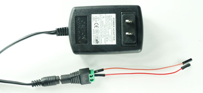
For the power supply for the Maestro, use a 6V, 3A (3000 mA) wall charger. Our robot is powered by this charger with the help of a DC female "balun" adapter and two male/female jumper cables, as shown below. The male ends of the jumper cables are inserted in the holes of the balun adapter and secured with the tightening screws. The female ends are connected to the power pins of the Maestro. We recommend using a red jumper cable for the "+" connector, and black or brown one for the "-" one. The use of the very inexpensive balun adapter makes soldering completely unnecessary.
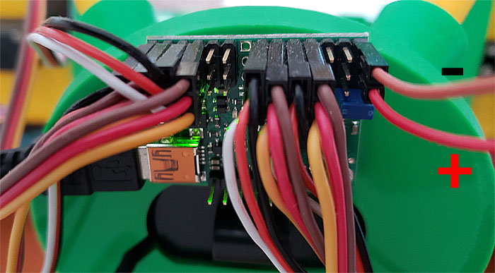
The servo controller should be attached to the back of the camera holder using two small wood screws. The image below shows the controller in its working position, with all the servo cables and power wires attached to it. The two power wires are on the right, with their polarity marked.
The purpose of the servo calibration is to find two key target settings for each servo's channel. For the gripper servos, the two target signals are for the neutral position and the 90° position. For the rack-and-pinion servos, the two target signals are for the "near" position (hugging the cube) and the "far" position (releasing the cube.) These numbers are determined experimentally using the Maestro Control Center software available on the Pololu web site and installed on your PC.
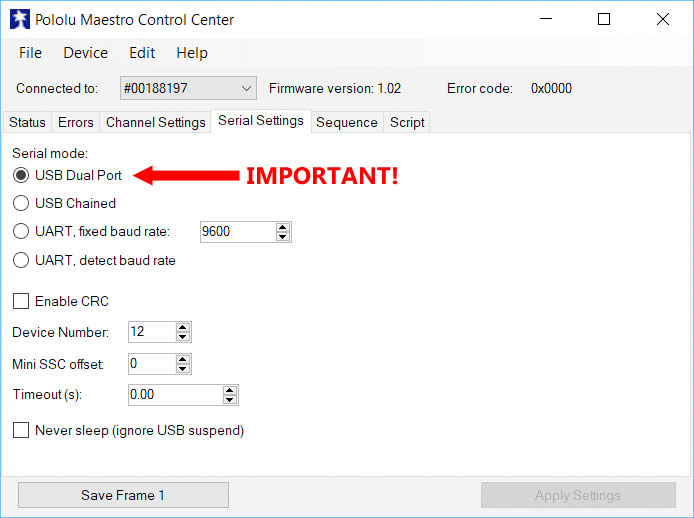
After firing up the Maestro Control Center, select the controller from the "Connected to" drop-down box. Go to the Serial Settings tab and select USB Dual Port for the serial mode. Then press Apply Settings.
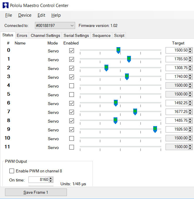
Then return to the main Status tab to calibrate your servos.
Also, for all the gripper servos (0, 2, 6 and 8 in our example) set the Acceleration value to 110, as follows:

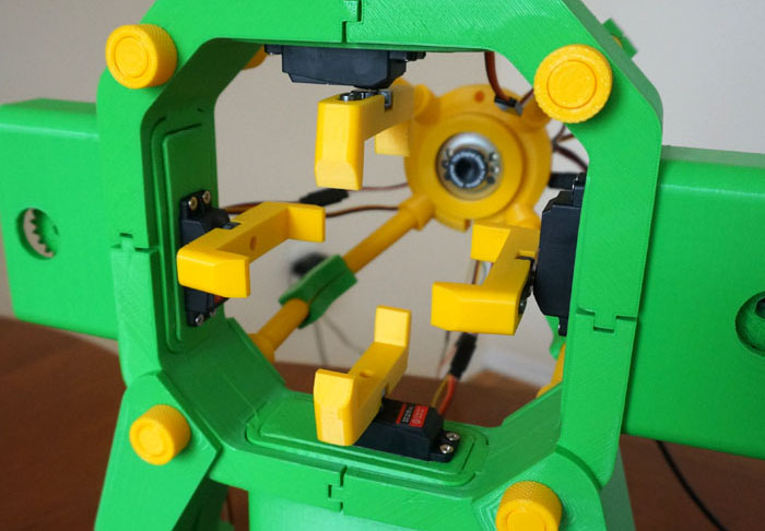
Begin the calibration by putting the sliders in the "far" position in which the front of the slider is flush with the arm, and put the grippers in the "neutral" position, as shown on the image below. Write down the "far" target values of the rack-and-pinion servos, and "neutral" target values for the gripper servos.
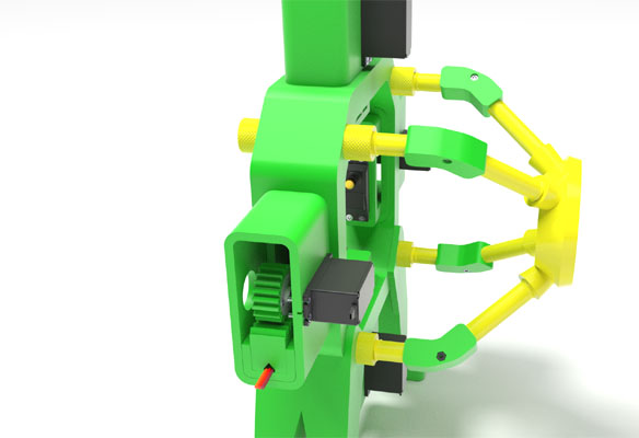
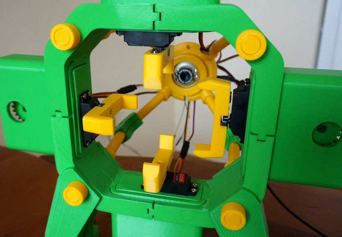
Next, determine the target value for a 90° rotation for each gripper servo. On the image below, the right arm's gripper servo has been turned 90° relative to its neutral position. Do this for each gripper servo, and write down the target values for all four.
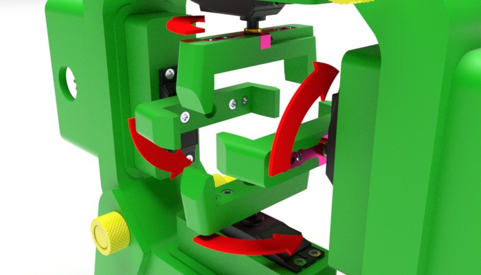
It is absolutely critical that all the gripper servos move from their neutral to 90° positions in the directions marked by red arrows on the image below:
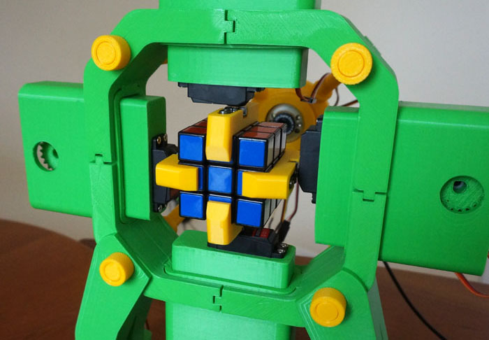
Finally, put the gripper servos back in the neutral position, and insert a Rubik's cube in the bottom gripper. Determine the "near" positions of all four rack-and-pinion servos in which the cube is tightly hugged and centered, as shown on the image below. Write down these target values.
Once acceptable target values for all servos have been determined, they need to be transferred to our application via its own user interface. The values can later be adjusted, if necessary.
Note that during calibration, the gripper and slider positions may need to be adjusted to allow a proper movement range. To adjust the position of a gripper, it needs to be removed from the gripper servo's shaft and then re-attached in a different position. Once the final position is found, the servo horn's clamp needs to be tightened with an Allen hex key. To adjust the slider's position, the pinion needs to be removed, the slider shifted as necesary, and then the pinion re-attached.
For more information on using the Maestro servo controller and its Control Center software, please refer to the Pololu web site.